Articles & Research • Principles of Sand Casting
Principles of Sand Casting
10th November 2026
Sarginsons Sand Casting – The Art of the Impossible
Sarginsons has long been one of the foremost sand casting foundries, with a particular specialisation in complex, safety critical prototypes, but its recent advances in casting simulations have changed everything. Sarginsons now delivers sand castings with higher, and more consistent, mechanical performance than any other sand foundry, resulting in less mass, less carbon and lower costs.
Casting has long been the black sheep of manufacturing, thanks to the sheer number of variables preventing accurate predictions of mechanical performance. All other foundries assume a homogeneous mechanical, fatigue, and TYE performance across the entire casting, which lead to errors in design. Sarginsons can accurately simulate mechanical performance at any point on a casting, which is a massive advantage in digital product design.
In addition to this clear lead in digital twin simulations, Sarginsons also operate four different methods of sand casting and a variety of new cooling techniques, that give it an unrivalled tool box for meeting clients aspirations. This allow Sarginsons to focus on replicating the mechanical performance of a production component in its sand cast prototypes – another massive advantage.
This superiority in casting technology and techniques, combined with the most comprehensive DfM service for Sand Castings, means Sarginsons is ideally placed to help design better components from the concept stage. This will ensure a cheaper and better performing casting, as any issues are effectively ironed out well before the first component is cast.
Sarginsons designs and manufactures its tools, patterns and fixtures in house, outsourcing only where a specific advantage is identified, which again gives it an advantage on those relying on third party tool design and manufacture.
What is Sand Casting
Any product shaped by being poured into an indentation in sand, that has usually been bonded, is a sand casting, and it has been in successful operation for over 5000 years. It is a low tech, simple process which produces components that are used in everything from high tech, sophisticated applications to the everyday and mundane.
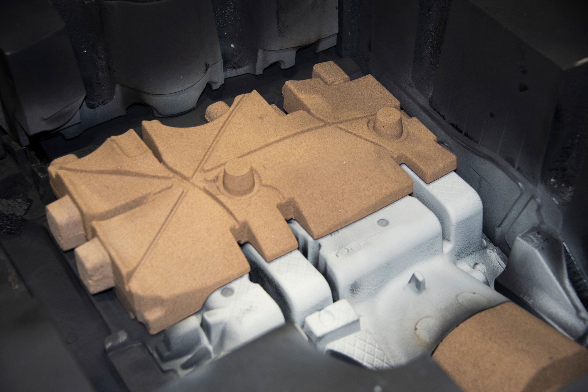
Traditional Sand casting relies on making a pattern of the object to be made from wood, moulding board or other. This pattern is used to shape a sand mould usually, but not always, built in two halves. Increasingly, however, 3D printing is being used to create the sand moulds, as it is quicker and allows increased complexity.
Once the metal has been poured in and allowed to cool the sand can be broken away and the component extracted. Normally, some finishing work is required to prepare the component before it is machined or heat treated. The components can range from grammes to tonnes in weight, and be comprised of virtually any metal alloy.
Why Choose Sand Casting
Although Sand Casting is an ancient methodology it offers advantages that make it very relevant to the demands of the modern world.
1. Versatility – Any size, shape, weight, alloy or quantity of part.
2. Heat Treatability – Enhance component strength through annealing.
3. Simplicity – The principles are easily understandable and implemented.
4. Adaptability – Quick modifications are readily achieved.
5. Affordability – Tooling is cheap, low volume production as well.
6. Scalability – Perfect for prototypes, but capable of mass production.
7. Rapidity – With 3D printed moulds, production components take hours.
8. Flexibility – Unlimited design potential, regardless of complexity.
9. Sustainability – Sand is 100% recyclable, whilst metal waste is reduced.
Today’s world is all about speed to market, flexibility of design and minimising waste all for the lowest possible price, which the world’s oldest manufacturing technique seems to suit well. And as casting technology overcomes it’s disadvantages of poor dimensional accuracy, poor surface finish and poor repeatability, the modern relevance of Sand Casting becomes ever greater.
The disadvantages of sand casting are also numerous but are slowly being mitigated as casting technology develops; one reason for Sand casting continuing to be the most popular casting medium.
1. Poor Finish – Surface finishes are not fine, but finer sands can improve.
2. Weaker – TYE strength is lower, but technology has advanced greatly.
3. Higher Porosity - Although reservoirs can improve porosity.
4. Dimensionally Compromised – A 4mm wall thickness is the minimum.
5. Poor Repeatability – Sand is inconsistent, so castings can be as well.
6. Hazardous Waste – Sand can now be 100% recycled.
7. Pattern Degradation – Sarginsons has a pattern shop for replacements.
8. Complex sand cores for internal spaces are tricky.
The development of casting technology, particularly the digital twin simulations developed by Sarginsons, has allowed sand casting to gain new relevance as potential weaknesses, at any point on a component, can be readily identified. This allows the TYE, stress and fatigue performance to be targeted, during the casting process, by way of advanced cooling, 3D printed cores and more controlled filling of dies from under-tool reservoirs.
Prototypes are typically made using sand castings but, although looking the same, can rarely replicate the mechanical performance of the production component. Until Now. The advances made in cooling, component design and directional solidification, combined with the awareness of the specific problem areas, mean that prototypes are not just Make Like Production (MLP), but can now be Made For Production.
Casting technology is a never ending pursuit of perfection in a world where the number of variables are seemingly infinite and largely uncontrollable. It is this battle in which Sarginsons has recently made huge advances and now claims to be able to deliver more capable and production-like sand cast components than any other foundry.
Sand Casting v Gravity Casting
The difference between sand casting and gravity casting, with a metal mould, is usually a question of the cost of the metal tool over a temporary sand pattern. And that’s usually a question of how many parts are required over what period as tool cost is defrayed over. Gravity castings also exhibit better dimensional accuracy, better finishes and stronger mechanical performance than sand castings although, as has already been mentioned, this difference is diminishing rapidly.
Sand Casting in Practice
1. Types of Sand Casting – Sand casting is defined by the material the mould is made from, but there are various ways that this mould can be filled. The method of pouring has a material influence on the quality and performance of the final casting.
a) Direct Pour/ Kalpur – A technique that involves pouring molten metal directly into the mould has many variations, such as KALPUR which combines a filter and feeder sleeve to improve the yield, quality, surface finish and directional solidification of the component. A dirtier method than others….
b) Counter Gravity – the metal is poured into the mould against gravity by building a reservoir underneath the mould. This eliminates shrinkage by maintaining a constant metal feed and reduces porosity but still allows turbulence in the metal during reservoir filling.
c) The Cosworth Method – Another variation of the counter gravity but using an electro-magnetic pump to ensure that the metal is pulled from the heart of the melt, reducing impurities and turbulence when filling. Also has a rotating tool which ensures uphill filling of the entire mould.
d) Low Pressure Sand – By creating a vacuum in the sand mould itself aluminium is gently drawn from a furnace underneath into the die. Less Turbulent filling and, as drawn from the middle of the melt, makes for a cleaner smoother fill. Slower than high pressure and has difficulty with tighter wall thicknesses but better mechanical strength.
2. The Alloy – All aluminium used in casting are alloys, most typically Aluminium silicon, as the silicon enhances castability, but the requirements of every casting differ. Some may need a focus on strength or ductility, whereas others may require high corrosion resistance or a better surface finish. The list of requirements is long. Whilst various base alloys, A356 / LM6 etc, may achieve some of these needs, particularly higher grades with fewer impurities, it is possible to enhance the structure and mechanical properties with chemical modifiers or other processes. This is particularly true of sand casting as solidification rates are slower, thanks to the thermal conductivity of sand.
Additives currently used include sodium, calcium, magnesium and strontium, all of which have specific effects on the silicon structure so enhancing a component’s structural performance. Before selecting a foundry, it is always worth investigating their level of metallurgical competence.
Alloys can be selected to enhance any of the following characteristics.
• Tensile Strength
• Yield Strength
• Elongation
• Corrosion resistance
• Ductility
• Shrinkage
• Hardness
3. The Sand – There are two principal sand casting methods, Green Sand and Air-Set. The first being bonded by moisture and clays and the second by chemical binders. Green sand casting is typically used for heavier, less intricate and less mechanically demanding components than is the case with Air-Set.
Other sands used include facing sand, for
4. Mould Creation
Once the casting and running system have been designed and the pattern and any core have been prepared, the mould for the sand casting is ready to be assembled.
The 3D pattern is secured in a wooden moulding box with a top (the cope) and bottom (the drag). The cope and drag are assembled to form a closed casting cavity and a mixture of high-grade silica sand, binder and catalyst is packed around it and allowed to harden into a mould.
As a sustainable sand casting company, Haworth Castings uses re useable wooden moulding boxes which:
a) are strong enough to retain their shape, hold weight and resist erosion,
b) allow gases formed within the mould to escape, and
c) are easily removed from the hardened mould.
Once hardened, the sand mould is released from the moulding box and can be prepared to create the final casting cavity for the manufacture of the metal component. If a core is prepared it will be added, along with any structures such as dypurs and sleeves which will be inserted to create the specific running system for this metal casting.
The sand casting mould is now ready in the casting foundry to receive the pour of liquid metal to create the final product.
5. Casting Design
Component Design in sand casting is critical to obtaining high quality, cost effective castings. It used to be regarded as more art than science, given the numerous variables of the sand casting process, but, with the advent simulations of solidification, stress, fatigue and topology, it is now all about the science, particularly when metallurgy is added to the mix. Sarginsons is a world leader in casting simulation technology and is now routinely involved at the design stages of several automotive OEMs development process. The grade, mix and sand used to form the mould, the alloy and additives required, the solidification and the required metal temperature can all be predicted.
Design for Manufacture is often used to describe the addition or omission of features that may affect or are used at a later stage in the manufacturing process. Casting design has more potential to benefit from DfM than other manufacturing methodologies, as it’s greater flexibility of design gives DfM more options. DfM for castings should include all the normal component features, detailed below, but also work with an eye to CNC Machining, Datum Location, Heat Treatment, Robotic Handling and so on, right through the component’s manufacturing process and that of any assembly of which it is a part.
Design Considerations of any casting will include
a) Detailed Prints – Foundries need detailed drawings of both the casting and the machined product. As well as details of any mechanical performance expected drawings should also detail any Radii, drafts, tolerances, defect levels, finish standards and inspection requirements
b) Draft angles – Frequently overlooked by designers, draft angles allow castings to be withdrawn from moulds more easily. Factors such as component design, depth and the process itself affect this. Typically 2%, a minimum of 1% for internal and external and internal features. Correct draft angles can even affect the cost and quality of the component.
c) Rounds and Fillets – introduced to improve the look of a casting, well designed rounds and fillets can distribute stress whilst minimising component stress. Corner Fillets can also help metal flow ensuring the mould fills correctly.
d) Split Lines – The point at which the mould joins needs to be correctly placed as it influences costs and component quality. Ideally, the split line should be as wide, flat and short as possible whilst being positioned at the corners or edges of components. In aluminium, it should be as low as possible. The line affects the number and size of cores, component weight, dimensional accuracy and filling direction.
e) Undercuts – created by the introduction of more complex features undercuts are designed to prevent a component’s removal during production. Ideally avoided undercuts can increase costs.
f) Cores – designed to introduce cavities or hollow sections into components cores are best avoided if possible as they introduce extra cost, complexity and time into the process. 3D printed cores are now massively increasing the range of what’s feasible in casting.
g) Cross Sections – maintain a consistent cross section across a casting is optimal but, in sand casting, but can be difficult to achieve in most component designs. Given variable cross sections it is important not to leave thicker sections isolated from the metal feed as they cool – porosity or tears can arise as a result.
h) Wall Thicknesses – Uniform solidification is the goal of any sand cast design, but this means the surface area ratio much be managed so as to ensure even solidification. To counter this many foundries increase mould or component thickness where they would be better introducing structural stiffeners or control wall thicknesses with gussets.
i) Corners And Angles – Poor cooling in the mould or casting can lead to heat building at sharp corners or junctions of the component which can cause stresses leading to crack, distortion and shrinkage.
j) Junctions – There are six or seven different types of junction, all of which can cause solidification issues there or in other parts of the component, because of metal pooling or becoming concentrated at a poorly designed junction. Cracks and shrinkages result which compromise the structural integrity of the component.
k) Casting Allowance – all molten metal will shrink, aluminium by more than 5%, as they solidify which has to be accommodated in the mould design. It is also crucial to include an allowance for machining if the component is to be combined in an assembly of some description.
Casting is often the first of many stages, including machining, heat treatment and coating. The quality and finish of the casting depends on which of these treatments is to be used and also on the final use of the component; visible surfaces will require a better finish that hidden ones.
6. The Gating System – The conduit through which molten metal fills the mould including the pouring cup, sprue and runners into the casting itself. Designing an effective and efficient flow of metal into the casting, through requires a deep understanding of casting technology, hydraulic principles (Bernoulli Equation and Reynolds Number) , metallurgy and the variables of casting itself. Properly designed systems enable efficient metal filling, without porosity enabling turbulence, whilst avoiding corrosion and premature cooling and hence shrinkage. Good gating systems also help remove impurities from the system.
There are 3 main types of gate, top, bottom, side, which can be pressurised or unpressurised. Top fed systems tend to generate more turbulence than bottom fed, such as counter gravity, systems which in turn risk premature cooling. Systems fed on the parting line tend to address drawbacks of both. Ingates, usually aligned with natural flow paths, are the points where the runners meet the mould, either vertically or horizontally, the casting.
To design an effective system, one needs to calculate the pouring time, based on factors such as materials, temperature, complexity, directional solidification size and section thicknesses. This allows the ingates to be sized correctly. Solidification simulations are used to determine the optimum sizing of these systems.
7. Runners, Risers and Reservoirs - Runners ensure metal leaving the sprue reaches the Ingates in sufficient volume to ensure that the runners are always full and, if the ingate is lower than the runner, allow impurities to be removed. Runners should be as short as possible, with no sharp edges corners to minimise turbulence, gas trapping and erosion; an extension can also trap slag,
The riser is effectively a type of reservoir which replaces metal lost through the volumetric shrinkage that occurs with solidification. The positioning is designed to ensure every part of the mould is readily filled leaving no cold or hot spots.
Reservoirs are used to bottom feed moulds where graduated and smooth filling is required effectively removing turbulence from the pour but filling first and rising into the mould: so called counter gravity casting.
Solidification studies are used but for safety critical or load bearing components, will also need to be supplemented by Sarginsons uniquely accurate digital twin simulations of TYE performance.
8. Metal Cleanliness – As performance demands increase, such as lower mass, so does the pressure on foundries to produce higher quality component with better physical and mechanical performance. Better metal cleanliness is one means of achieving this quickly and cheaply, particularly if scrap constitutes a proportion of the melt. There are several stages and methods of doing this.
a) Perfect Preparation – Buying high quality ingot direct is the simplest method of ensuring quality metal but, in addition, accurate and rapid testing is critical. Sarginsons are one of very few foundries to use the ABB Prefil Filtration gas analyser for real time inclusion analysis as well as standard metallurgical, spectrographic and K-mould analyses.
b) Best Practice – There are a number of issues that need correct metal management, such as the use of correct temperatures (particularly when adding alloying elements), regular melt skimming, daily furnace cleaning and minimising turbulence on metal transfers.
c) Degassing – Most foundries use a rotating degasser to inject a reactant into the molten metal to reduce hydrogen levels, as well as to reduce alkali metal and inclusion impurities. Sarginsons employ the SMARTT software to automatically optimise the degassing process (reactant flow rate, rotor speed,) by automatically allowing for issues such as ambient temperature, humidity, and metal quality.
d) Filtration – 3D printed ceramic foam and tube filters are a recent development that ensure exact filter repeatability allowing flow rates to be calculated perfectly. This facilities the removal of non-metallic impurities which greatly assists metal cleanliness. Filters also help reduce turbulence. Sarginsons have their own 3D ceramic printer, a VX500.
e) Constant Testing – Every foundry operates a regular quality check on every melt as well as 3 or 4 time daily checks on metal quality in every part of the process.
9. The Pour – A simple but vital part of the entire metal cleanliness and component quality process is the pouring of metal into the mould. Careful control and technique is vital to maintain temperatures, improving component quality, and lowering turbulence, reducing the entrapment of gases.
Temperature control is vital as the chemical and physical properties required will be adversely affected otherwise, producing a weaker component. There are several factors which can affect performance
a. Pouring Rate – Dependent on the size of the casting, thinner ones requiring a faster pour, it is vital this is sufficient to reach all parts of the mould before starting to solidify but without overwhelming any part of the gating system.
b. Fluidity – the fluidity of metal is dependent on temperature, metal composition, crystal structure and equipment condition.
c. Pouring points – Multiple pouring points may be used to introduce metal to the mould as this helps reduce the risk of solidification occurring prematurely, particularly in thinner sections.
d. Pouring Equipment – Automatic pouring units are available but are generally used for volume production whereas crane and robot controlled systems are also available.
10. Venting and Gas – Essential for avoiding the adverse effects of gas (pin holes, misruns and cold shuts) entrapped in cores, moulds, coatings and binders during the solidification and pouring of castings. Cores need venting more than moulds, because a greater percentage of the sand is in contact with the hot metal and gas is less able to escape, because room is limited by more complex geometries. Gases also pressurise the mould cavity, particularly with more impermeable moulds, hindering flow of the metal
The gases arise from the release of dissolved gases as molten metal cools, the act of heat on the chemical binders or water in the mould or core and even from humidity in the work environment. The gases emanating from the cores are post filling of the dies and pose few problems, whereas gas generated from the moulds can create considerable back pressure which may negate choke points – venting from the top of the mould cavity is advisable and will also serve as a fill indicator.
Vents should be mounted directly on the pattern, as manual methods are uncontrolled, with their size controlled by the weights of the casting, core and mould. Vents can cause defects, run-outs, if not correctly managed
11. Smarter Cooling - Cooling is vital in sand casting because it helps achieve the desired mechanical properties and dimensional accuracy of the final product. Proper cooling rates also help prevent defects such as shrinkage cavities and internal stresses.
a) Reduces scrap: A sand casting cooling system can reduce sand-related scrap rates.
b) Improves sand consistency: Maintaining the temperature and moisture of the sand within the desired range can improve the consistency of the sand.
c) Reduces casting defects: Casting defects such as sand inclusions, swells, and erosion can be significantly reduced.
d) Improves productivity: A sand cooling system can enhance productivity.
e) Reduces time and labour: A sand cooling system can reduce time and labour in the finishing department.
The cooling rate, or how quickly the casting cools, has a direct effect on the structure and properties of the cast material:
a) Grain size - A faster cooling rate results in a finer grain size, which can lead to higher strength properties.
b) Phase transformations - A faster cooling rate can shift phase transformations to lower temperatures.
c) Glassy structure- A cooling rate that is equal to or higher than the critical cooling rate can result in a glassy structure.
Factors that affect the cooling rate include:
• Heat flow: The greater the temperature difference, the faster the heat flow.
• Casting geometry: The geometry of the casting can significantly impact the local cooling rate.
• Chills
• Cooling systems
12. Sand Cast Finishing – A critical stage in aluminium sand casting is finishing, the process used to prepare cast components for industrial and commercial use and to give the component the desired surface texture.
Finishing will
a) remove excess material or surface contaminants
b) enhance aesthetic qualities
c) act as a pre-treatment for other finishing processes.
Finishing service involves
a) Fettling: Removes excess material and flash from the casting using hand tools or robots
b) Linishing: Grinds or sands the casting to improve its surface flatness
c) Shot blasting: Uses stainless steel shot to remove contaminants and create a uniform finish
d) Shot peening: Uses finer ball bearings to enhance the surface finish and protect against surface cracks
e) Rumbling
A gentler blasting process using polished stones to produce a smoother, more tactile surface.
f) Coating: Includes powder coating, wet painting, and anodising
g) Moly spraying: Provides added protection for extreme temperatures.
h) Anodising: An electrolytic process that thickens the natural oxide film on aluminium to increase corrosion resistance
i) Zircon sand: A mould wash that can improve surface finish, but is expensive and not readily available
Make Like Production – The biggest dichotomy in casting is that prototypes are made using totally different processes and techniques from production parts, so they display totally distinct mechanical performance, which makes their function as prototypes limited. This can now, to a large extent, be overcome with simulations of TYE performance and then using a whole range of newly developed techniques to manipulate TYE to match that of the production components. Sarginsons is probably the most advanced foundry in the world at TYE simulation and control to Make Like Production prototypes as close to actual as possible.
This trend to make cast prototypes more accurately reflect the performance characteristics of production parts, has been both enhanced and made more complicated by the trend towards casting larger parts and to casting one piece assemblies, such as sub-frames. The ultimate expression of this are giga castings. So with huge investment in the this larger capacity it is ever more critical to be able to test actual components, with the correct TYE mechanical characteristics.
Sarginsons simulations, particularly with early results of its PIVOT research program are world leading.
Enhancing TYE Mechanical Strength
Pattern Manufacture
Control and mastery of the very latest in pattern design thinking and technology is a crucial part of ensuring complex casting requirements can be accommodated, particularly where TYE and Fatigue performance needs to be manipulated. This is why Sarginsons bought leading sand pattern manufacturer, Pattern Solutions.
At its most mundane, sand patterns have to exactly replicate the end product design, with an allowance for machining and metal contraction during cooling. Pattern designers need drawings or models for the casting and finished product, alongside details like volume and surface finish. The designers can calculate metal flows, runners and risers, cavities and cores. The pattern itself can be CNC machined or 3D printed from high quality resin.
Cores: 3D, Sand, Inorganic and Organic.
A component’s internal features, or cavities, are created using cores, made of sand and resin. These can be manufactured in a number of ways but three in particular.
Hot Box Cores – Fine graded, alkali free, resin coated quartz sand is hardened, with the help of a catalyst, directly after being blown into a pre-heated, 230⁰C, core box, producing a hard shell. These cores are strong, capable of great dimensional accuracy.
The most typically used resin is Furan which gives decent strength, low gas emission, good dimensional complexity and is quick to cure. These cores may be susceptible to cracking, because of the rigidity, have higher tooling costs and may struggle with variable wall thicknesses. Phenolic or Urea based binders may be used where lower gas, better detail or higher strength is required. Core boxes are normally metal, sealed and contain their own heating elements with a focus on even heating to ensure a full hardening.
The Cold Box process – By not heating the cores production volumes are greatly increased and bigger cores can be made more easily, so the majority, 70%, of cores are made this way. Different low alkali sands can be used with hardening occurring by way of a concentrated amine mist, which can be reduced as binder quantities are reduced. The binder is usually a two component organic system, phenolic and polyisocyanate, which hardens at room temperature.
New developments in resin synthesis have increased the binder reactivity improving productivity and strength, allowing a reduction in the amount of binder used. These new resins also reduce gassing time and the tendency to stick.
3D Printed Ceramic & Sand Cores - 3D printing offers massive potential for core manufacture and the overall possibilities of casting itself. They are faster, no need for core boxes, allow greater design complexity and dimensional accuracy, and are more durable. They also reduce waste, downtime and costs whilst enabling higher quality and more customisation.
Ceramic cores are generally, but not exclusively, used in investment castings where as 3D printed sand cores are direct replacements for their hot and cold box predecessors.
Increasingly the market is seeing the development of a hybrid approach to sand casting by pairing conventional sand moulds with 3d printed cores. This approach allows greater complexity, and speed whilst integrating easily into existing foundry operations and all with less waste.
Inorganic Cores - Sarginsons is one of the first foundries in the world to buy a 3D sand printer with an organic binder. Not only does this greatly reduce the carbon footprint of the castings but also reduces concerns about gas emissions disrupting the filling of sand moulds, Inorganic binders using water than organic compounds for binding.
Sarginsons Sustainability
Recycling sand
We recycle 100% of our sand in our sand casting foundry, giving significant environmental benefits whilst assuring high-quality metal castings for our customers.
Recycling raw materials
Many of our other raw materials, such as metals, are reused in the casting process – only a minimal amount is sent to scrap.
Managing our emissions
As a leading casting supplier, we also manage our emissions responsibly. Our facilities are inspected every two years to check on our emission levels.
Torrington Avenue, Coventry,
West Midlands, CV4 9AG